7 Tips for Choosing the Right Tapered Motor Shaft?
Selecting the right Tapered Motor Shaft affects alignment, torque transfer, vibration, and equipment life. A poor choice can create expensive problems before the motor reaches full speed. Small errors matter.
In practical equipment reviews, engineers often examine shaft dimensions before discussing brands. They check the taper angle, large and small diameters, usable length, keyway size, and material grade. Fit comes first. A shaft may look suitable on paper, yet fail when exposed to shock loads or frequent starts. The motor’s rated torque, operating speed, and coupling design must match the shaft’s real working conditions. Dust, moisture, heat, and corrosive chemicals also deserve attention. These details are easy to overlook.
This guide presents seven practical tips for choosing a dependable Tapered Motor Shaft. It explains how to verify measurements, evaluate load capacity, compare materials, and confirm compatibility with the motor and driven equipment. Clear manufacturer drawings and traceable test information can support safer decisions. However, specifications are not always complete. Ask questions when tolerances, surface treatment, or balancing data remain unclear. Details decide performance.
A careful selection process can reduce misalignment, premature bearing wear, and unexpected downtime. It can also make installation easier, especially when technicians work in tight spaces. Still, no general guide replaces an application-specific engineering review. The correct shaft depends on the complete system, not one attractive dimension. Small compromises can become costly.
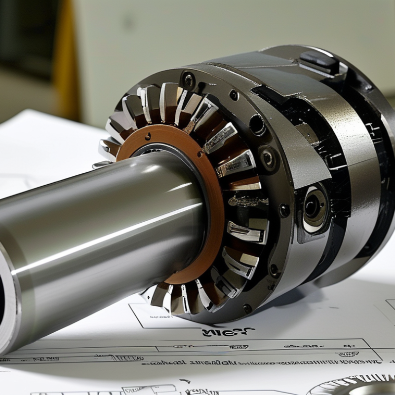
Define the Application Requirements for a Tapered Motor Shaft
Define the Application Requirements for a Tapered Motor Shaft
Choosing a tapered motor shaft starts with the machine, not the shaft catalog. Record required torque, operating speed, duty cycle, and starting load. A conveyor running continuously needs different capacity from a lightly used positioning device. Measure the mating hub carefully, including taper angle, large and small diameters, shaft length, keyway, and shoulder position. A small dimensional error can create vibration or poor contact.
Tip: Check the real load, not only the motor rating.
Radial and axial loads also matter. Note where the load acts along the shaft, because distance from the bearing changes bending stress. Include shock, reversing motion, temperature, dust, moisture, and cleaning chemicals. These details influence material selection, surface finish, corrosion resistance, and sealing needs. In practice, application data is sometimes incomplete. That is a weakness worth addressing before ordering.
Tip: Confirm the fit with drawings and physical measurements.
Allow space for installation and future maintenance. Verify whether tools can reach the retaining hardware and whether the shaft can be removed without dismantling half the machine. Specify acceptable runout, balance, and tolerance requirements when speed is high. A quick visual match may seem reasonable, but it cannot replace torque calculations or a load review. When uncertain, have a qualified mechanical engineer check the design and document the assumptions.
Choose the Appropriate Taper Design and Connection Method
A tapered motor shaft transfers torque through its angled surfaces, not through the key alone. Choosing the taper design requires careful attention to load, speed, and assembly space. A shallow taper offers strong seating and easier release. A steep taper may simplify removal but can loosen under vibration if clamping is inadequate.
Check the shaft diameter, taper angle, contact length, and shoulder position together. These dimensions must match the mating hub precisely. Even a small mismatch can create uneven contact marks near the shaft end. I usually apply a thin marking compound during a trial fit. Rotate the hub by hand, remove it, and inspect the contact pattern. Full contact is the target. Real installations are less perfect.
The connection method also affects reliability. A keyed taper can handle repeated torque, while a clamping nut provides axial retention. Some applications need both, especially during reversing cycles or frequent starts. Use the specified tightening torque and clean all mating surfaces before assembly. Oil on a dry taper can change the holding force. Do not rely on visual alignment alone. Measure runout with a dial indicator after installation, preferably near the hub face. If the reading exceeds the equipment tolerance, inspect the taper, key, and bearing seating before operating the motor. A rushed fit often becomes a costly vibration problem.
7 Tips for Choosing the Right Tapered Motor Shaft
Choose the Appropriate Taper Design and Connection Method
The chart shows the calculated included taper angle for reference taper ratios. The calculation uses included angle = 2 × arctan(1 ÷ (2 × taper ratio)), where the taper ratio is the diameter change per unit of axial length. A smaller included angle generally provides a longer engagement surface, while a larger angle can simplify release and assembly.
1. Match the taper ratio to the required torque, axial load, and available shaft length.
2. Use a self-holding taper only when reliable seating and controlled removal are available.
3. Add a key, spline, or clamping feature when the joint must transmit positive torque.
4. Use an axial nut, drawbar, or retaining collar to prevent separation during operation.
5. Specify fit, surface finish, and contact length to control runout and fretting.
6. Check material strength at the smallest shaft diameter and at keyways or threads.
7. Design for inspection, lubrication, and removal without damaging the mating components.
Reference geometry only: final taper dimensions and connection details should be verified against the applicable engineering standard and operating conditions.
Verify Quality, Maintenance Needs, and Supplier Reliability
7 Tips for Choosing the Right Tapered Motor Shaft?
Verify Quality, Maintenance Needs, and Supplier Reliability
A tapered motor shaft should fit accurately, not merely look polished. Measure taper angle, keyway size, shoulder position, hardness, and total indicated runout. Request material certificates and dimensional inspection records for every production batch. ISO 20816 vibration guidance can support acceptance checks after installation. Small alignment errors become expensive quickly. The U.S. Department of Energy reports that motor-driven systems use more than 70% of industrial electricity. Shaft defects can therefore increase vibration, heat, and energy waste across entire production lines.
Maintenance evidence matters as much as initial quality. Ask for recommended lubrication intervals, corrosion protection, seal requirements, and replacement limits. Review the shaft’s expected fatigue performance under actual loads, including starts, stops, and shock conditions. IEA’s Energy Efficiency 2023 report estimates that electric motor systems consume about 53% of global electricity. This makes preventable mechanical losses worth investigating. Still, maintenance schedules are not universal. A dusty workshop and a clean assembly room should not receive identical advice.
Supplier reliability needs measurable proof. Check on-time delivery records, traceability, corrective-action reports, warranty response times, and inspection capabilities. An independent factory audit can reveal weak process control. Require a sample shaft before approving volume production. Verify that its dimensions match the drawing, not just the supplier’s certificate. The perfect checklist does not exist. In practice, one overlooked tolerance can expose a larger weakness in communication, testing, or accountability.